Skateboard Deck Design
Name: Aayush Amrit
ENG ME360
February 17, 2022
Goal
The goal of this project is to design a lightweight skateboard deck which will withstand the stress in worst case scenario and deflect less than the maximum allowed deflection. The skateboard is designed using Solidworks. The deformation and the stress on the skateboard under load are analyzed using finite element analysis(FEA). Material selection is based on outside research.
Constraints
The skateboard should be able to withstand 180 lbs of force and have a factor of safety of 3 in the worst case scenario. The weight of the person should not cause a deflection of more than 0.375 inches at any point across on the deck. The deck should be supported by a roller at the front truck and a pin joint at the rear truck.
Summary of Relevant Information
This skateboard is designed for people who are interested in doing stunts. The length of the skateboard is 28 inches, which is on the lower end of the average skateboard length of skateboards (28''-32''). This makes the skateboard maneuverable. The skateboard is also designed to deform very less to make sure the rider has more control while doing stunts. The factor of safety of the skateboard is a little over 3 to make sure it can withstand the force when the rider jumps on it. The skateboard has a factor of 3 even when the rider stands at its center on one foot, which results in the weight of the rider being distributed in a smaller area on the deck.
Design Decisions and Justifications
The skateboard deck is 28 inches long and 8 inches wide. I chose these dimensions to make the skateboard easily maneuverable. The skateboard is 0.7 inches thick. The tail of the skateboard is angled at 30 degrees and the nose of the skateboard is angled at 20 degrees. This is to make sure the rider has space to put their feet on these to push against them to do a stunt. The tail and nose of the skateboard are filleted to remove some material and thus reduce the weight. Out of the 28 inch length, the flat part of the board is 18 inches long and the tail and the nose are 5 inches long each. The flat part of the deck is 64.6 percent of the total length to make sure that the user has enough place to keep both their feet comfortably on the skateboard. The tail and the nose are 5 inches in length to make sure that the rider has ample space to put their foot on while doing stunts.

Material Selection
The material considered at the beginning of the design process was carbon fiber as it is lightweight and strong. But, later in the process wood was thought of as the better material to make the deck. This is because carbon fiber is very expensive, extremely brittle and thus tends to break easily and is hard to machine. Wood is cheap and easy to machine. It is also elastic and has high impact resistance. Maple wood was considered to make the skateboard but it is not a material listed in Solidworks so Balsa wood was used instead. Balsa wood is one of the woods used to make skateboards in the industry and this is the only type of wood that has its Young's modulus and tensile strength listed in Solidworks. The modulus of elasticity of Balsa wood is 3 x 10^9 N/m^2 and its yield strength is 2 x 10^7 N/m^2

Modelling and FEA
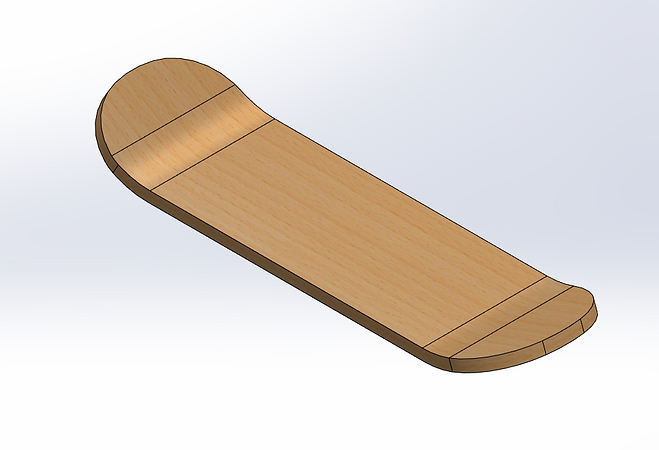
The skateboard deck was designed using 3 planes, each with one sketch on it. Of the three planes used, one was a primary plane (top plane) and the other two were planes created using the reference geometry feature on Solidworks. A rectangle was drawn on the primary top plane and was extruded to form a cuboid. This made the flat part of the skateboard. The two reference planes were made at a certain angle to the skateboard and passed thorough the lower edges of the shorter side of the flat part. Then, the shape of the tail and nose were drawn on each of these reference planes and these were extruded to the same thickness as the flat part. The sketches of the nose and the tail were made on reference planes keeping in mind that the angles of nose and tail might need to be changed in the future. Changing the angle of the the reference plane would change the angle of the corresponding feature (nose or tail). Then the nose and the tail were smoothly merged into the flat part of the deck using the fillet feature.
FEA was done to analyze the stress and deflection under worst case scenario. It was assumed that a person weighing 180 lbs stood right in the center of the skateboard with all the weight on one foot. The skateboard deck is assumed to be connected to the front truck by a roller and the rear truck by a pin joint. To make the front joint a roller, two perpendicular directions of motion of the point of connection were restricted and motion along the length of the skateboard was allowed. For the pin joint, all three perpendicular directions of motions were restricted. The mesh created to do FEA was fine enough to have at least two triangles between any two parallel edges of a face.
 Modeling.png |  Force Distribution.png |
|---|
Design Optimization
The skateboard was remodeled multiple times to reduce weight and improve its maximum load capacity. Initially, the skateboard was designed to be 0.5 inches thick and did not have very visible nose and tail (figure 1). This skateboard design was put under load using load using FEA. Looking at the results, it was clear that the skateboard was not able to meet the required load capacity with a factor of safety of 3. So, the thickness of the skateboard was increased to 0.8 inches to make sure it has a factor of safety of 3 under worse case loading. This increased the factor of safety to well over 3 so the thickness of the skateboard was reduced again to 0.7 inches to minimize weight and keep the factor of safety only a little over 3. These changes also meant that the skateboard had a way lower deflection that the maximum allowed value when compared to the design with 0.5 inch thickness. Then, the angles of nose and tail were increased and they were made longer to make the skateboard more suitable for doing stunts. It was noticed filleting the outer edges of the nose and tail did not have a lot of impact on the maximum stress load capability so they were filleted to reduce the weight further.
Results, Conclusion and Future Work
The final design of the skateboard has maximum stress of 6.457 x 10^6 N/m^2 in the worst case scenario. As stated above, the yield stress of balsa wood is 2 x 10^7 N/m^2. This means that the factor of safety of the final design is 3.089. The maximum deflection is 0.04 inches which is way below the allowed 0.375 inch deflection allowance. The skateboard deck weighs 0.89 lbs.
While the length and width of this skateboard are similar to the skateboards available in the market, this skateboard deck needed to be made a little thicker to meet the stress and deflection requirements. This may be because this skateboard deck is made of one layer of wood while most skateboards in the industry are made of multiple thin layers of wood. This results in the layers sliding on each other under load and thus the deck is able to withstand a higher load for a given thickness. So, this skateboard design can be improved by splitting the skateboard deck into multiple thin layers.
 Stress Plot.png |  Displacement Plot.png |  Factor of Safety .png |
|---|